
John R. Bentley 2012.
construction of
A Stainless Steel Fuel Tank
for the model D-type boiler
December 28, 2012.
John R. Bentley 2012.
construction of
A Stainless Steel Fuel Tank
for the model D-type boiler
The burner unit of course requires a fuel supply. Since the windbox construction is essentially completed, the time seemed appropriate to begin construction of a fuel tank. I felt that 10 ounces (300 cc) of methanol should be sufficient for normal length runs. By my calculation (and allowing for some air space in the tank) that amounts to a total of about 5000 BTU able to be produced over the total run time of the fuel. Obviously that would equate to a theoretical rate of 10,000 BTU per hour during a half-hour run. The usual burner inefficiencies will reduce that figure. However because methanol requires far less cold air to be drawn in for proper mixture than other common liquid fuels, the air cooling effect in the boiler furnace is correspondingly lower.
With the completion of the tank and fittings it will be possible to turn attention to construction and testing of the actual burner and vaporizer unit - an interesting challenge which I look forward to with great delight.
As of December 15, 2012 this fuel vessel has passed all hurdles in testing. The hydraulic test has been carried out at 250 psi. It will really only be used at about 25 psi working pressure unless I am forced to switch to paraffin or petrol, where 60-80 psi is more probable.
Pounding out the dished and flanged heads in stainless steel was an interesting experience!
.jpg)
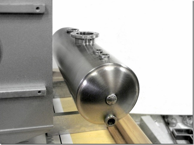
The large threaded opening is for methanol filling. The filler cap will also serve to contain a safety valve perhaps supporting a tall vent stack. The dimensions of the tank are 170 mm x 50 mm (6 5/8" x 2") and it holds 300 cc (10 oz). It might be painted when all is finished.
The four pictures below are only mock-ups for the camera... the final position of the fuel tank will be beside the boiler, but carried in two metal saddles atop pseudo concrete piers to match the two piers supporting the boiler. The tank height will be slightly less than halfway up the boiler to permit gravity feed to a wick chamber at the front of the burner for starting, but not to allow flooding. The boiler casing and stack are presently painted for protection in a temporary silver-grey.
The entire windbox and burner assembly is missing from the front face
(as well as the fittings of course)
.jpg)
Another shot with the windbox in position on the boiler
.jpg)
The following two photos were taken after silver brazing and pressure testing
(the apparent grain in the above picture is actually "sputtered" spray paint on the boiler casing.
The final painting is still in the future.)
- My construction began with the tank heads -
(they were formed from stainless steel disks between steel dies)
Turning the bottom forming die from 12L14 steel
(using the Craftex 7" x 8" mini lathe)
.jpg)
Using a profile gauge to record the curve for the next step
.jpg)
Don't look at the pencil or the curved line on the paper!
(check the matching convex profile on the left side of the gauge)
.jpg)
Using the convex profile from above to check the concave die
.jpg)
What a great contraption!
Bringing the turned surface to a more uniform shape with the Dremel
(Yes, I turned the lathe very slowly in reverse for this operation)
.jpg)
The surface looks rough but it has a fine texture and is excellent for holding abrasive paste
Lapping the two die surfaces with valve grinding paste and oil
.jpg)
That seemed to work out well
.jpg)
Cutting off some 304 stainless steel tubing for plate material to make the tank heads
.jpg)
Making a longitudinal cut through an unrelated existing hole
.jpg)
Ready to reclaim a bit of sheet metal :-)
.jpg)
This stuff is over .070" (1.87 mm) thick and doesn't just bend in your hands!
.jpg)
Flat at last!
.jpg)
By the way that backdrop is Flexoid gasket material made by Jointine Products Ltd. in Lincoln, England
(great people! they are also the manufacturer of Oakenstrong which was normally included with Stuart castings sets)
Lazy, man! - why bother measuring, this little thing is just the right size to trace around:-)
.jpg)
Two blank disks cut out with the 4" x 6" horizontal/vertical bandsaw
.jpg)
I borrowed this drawing force chart from Wikipedia:
- it shows that stainless steel takes considerable force to form compared to other metals
.jpg)
Ready to form a tank head from a disk
.jpg)
Top die with a hole for the locating pin
(where a central stay will be located in the finished tank)
.jpg)
Waiting for the vise
(and a hammer)
.jpg)
Squeezing a curve into the disk using the vise
(Of course the original pressing took place with the setup located in the middle of the vise jaws.
I moved it out to the side of the jaws for a good hammer swing while forming the flange.)
(technically speaking this is called open-die, cold press forging)
.jpg)
At this time the flange was ready to be pounded around the form on the left
The "open die" term refers to the fact that the metal is not completely encompassed by the dies. My reason for leaving the right side smaller was to allow the hammer better access when forming the flange. As you will see in the second picture down, this causes a tiny amount of upsetting (thickening) immediately outside the smaller die, visible as a ring near the periphery. This is a good area to have some extra metal because as the flange is subsequently formed the metal is normally drawn (stretched & thinned) over the corner radius. The end result of using this open die method was a very uniform thickness tank head which has also been nicely toughened by the cold forming.
(from pre-owned 304 stainless steel tubing)
The resulting dished head
(before flanging)
.jpg)
The ring indicating the location of the earlier upsetting outside the smaller die
(but now ready to be drawn flush again during flanging)
A light sanding is required to bring this component to a finish
.jpg)
Touching up the finish with a foam sanding block in the Taig lathe
.jpg)
One finished fuel tank head leans against one of the the two 12L14 steel dies between which it was formed
(a blank disk for the other head lies in the foreground)
.jpg)
A partially flanged head with a completed head to the right
.jpg)
Some pounding with the hammer yet to go on the left one !
.jpg)
Finished heads before drilling for a bush and enlarging the central holes for the longitudinal stay nuts
.jpg)
I am sure there is a correct way to do this, but I used this method :-)
.jpg)
When the hole was drilled out to near the desired size, I placed the head flat on the table and used a reamer so that the finished hole would be parallel to the tank axis.
It's finally time to build the tank!
.jpg)
Trimming the ends in the Craftex lathe
.jpg)
Using the "Bentley 2002" steady rest
.jpg)
Ok - the diameter was too large and wouldn't fit - so I had to switch the ball bearing arms around the other way!
Drilling for three top fittings
I will be making use of the large existing hole in the tube as well
.jpg)
Drilling a big hole for the fuel filler plug/safety valve
.jpg)
The bottom requires one fitting and two blind bushes for mounting the tank
.jpg)
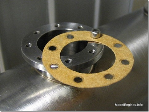
Constructing the inspection manhole
.jpg)
The finished manhole - and the cover ready for parting off
.jpg)
Tapping a long stay-nut by hand in the Craftex mini lathe
.jpg)
The tank components except the two blind mounting bushes
(the stay-nut and a bush are already silver brazed into the front head)
.jpg)
Note that the use of a central stay is a big bonus as it was not included in the tank's original pressure calculations
(it is not required at this tank's rating and is only there to provide an extra safety factor)
First operation - silver brazing the manhole and bushes
(this joint went very nicely - cleanup to follow)
.jpg)
I coated these bushes with silver brazing alloy - then heated and let them drop into place
(the screws are only to check alignment during brazing)
.jpg)
Looking up at the top of the shell from the inside
.JPG)
The brazed joint is clearly visible where the manhole tube protrudes downward through the shell
This is the inside of the bottom of the shell showing the bush for the fuel level gauge glass
- the tall object behind it is a blind tank-mounting bush
.jpg)
The bushes were brazed from the outside - this inside view reveals the silver alloy penetration was excellent
I learned some important lessons about silver brazing of 304 stainless steel, the main one being that the procedure is essentially the same as with copper, except 304 SS is most unforgiving of any deviations from the "rules". In return for that nuisance there is the advantage that the heat can be kept localized easily, providing better control and preventing re-melting of previously-brazed joints. It was possible to heat one end of this 6.75-inch-long tank red hot while the other end remained cool to the touch. The use of any chemicals in cleaning after brazing this metal is a questionable practice and I simply avoided that procedure and cleaned it up the hard way. My Lomo stereo microscope was put to good use in doing thorough post-cleaning inspections.
The shell wall thickness was more than twice the calculated requirement due to available tubing.
Ready to braze-in the rear head
.jpg)
Turning a small recess at the ends enabled me to leave the head flange at maximum thickness.
The flux is on...
.jpg)
This was the last of the brazing - the tank was then ready for testing
I decided to use Flexoid for the manhole cover gasket - it has good resistance to methanol
The finished tank was tested hydraulically to 175 psi for a half hour, raising to the final test pressure of 250 psi.
(although a maximum working pressure of 125 psi is indicated by this test, in practice this tank will likely only be worked at about 25 psi)
Sorry about that residue showing on the tank! - I washed it with hand soap after filling it for the test and it was not totally rinsed on the outside
.jpg)
(the two round black objects above are the bases of quartz desk lamps used as photo lights)
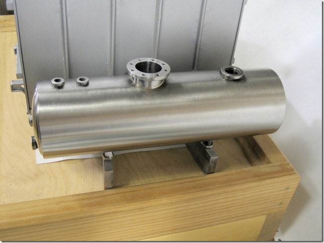
If the universe unfolds as it should, the small top front inlet will provide vapour return (and supply pressure) from the burner vaporizer. The second small outlet behind it (and its mate underneath) will hold a glass fuel level gauge on the right hand side as well as a tank drain valve at the bottom. The front opening below the central stay will hold a stop valve for the fuel feed to the burner and the large flanged hole is an inspection manhole.
.jpg)
Still a long way to go but it shows promise!
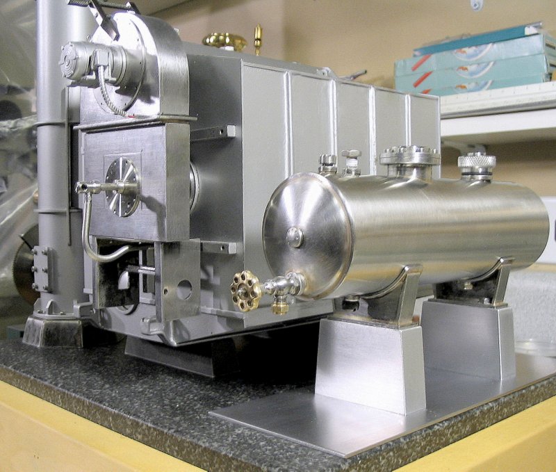
A view with the burner now painted (as the main boiler casing will be eventually)
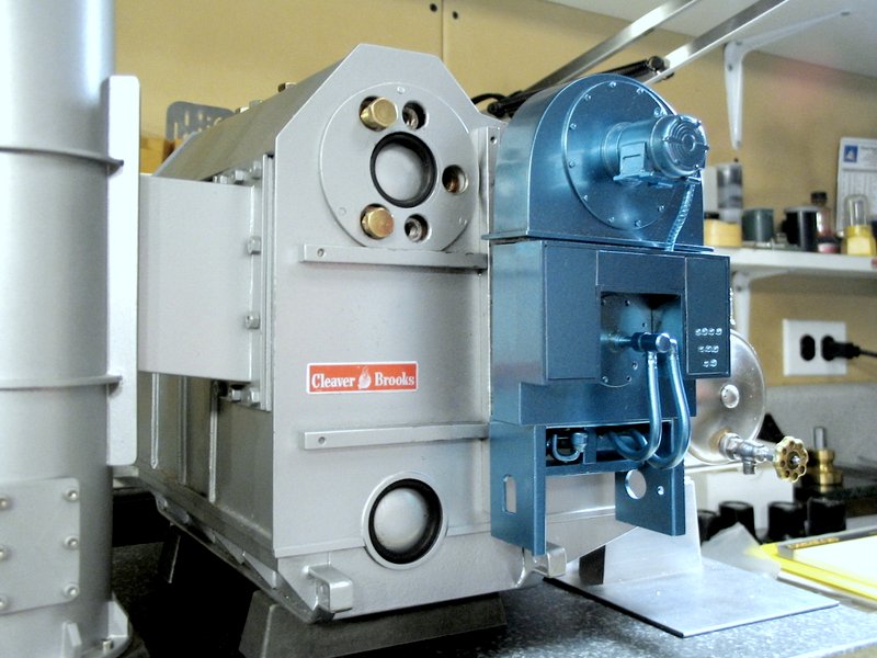
However since this picture was taken as some work has since resumed - including the construction of the fuel tank cradle and supporting piers as well as two stainless steel safety valves for the boiler in 2013 and recent work on the burner in October 2015.
The fuel level gauge will differ slightly from a standard boiler water gauge in that it must span the full depth of the tank, rather than only showing the narrow permissible water level range allowed in a typical steam boiler. With all of this stainless steel my model may start looking more like a dairy than steam plant!
This page brings the description of this yet unfitted watertube boiler plant to date as of October 30, 2015.
Be sure to check out the "Fuel Tank Fittings" page 11 next for later work.
You are on Part 10