
John R. Bentley 2009.
2008 - 2009.
John R. Bentley 2009.
Model Watertube Boiler
- Insulating the Enclosure -
On the previous page I forgot to show the boiler hanging from cables by its lifting lugsGood balance! - I must have copied the prototype's weight distribution fairy well... brag, brag, brag!Insulation:Here is the ceramic rigid felt - it's nice stuff!The ceramic blanket is thicker but much less solid(however it has tremendous insulating capabilities)A single layer of this material placed on the palm of a hand will eliminate any sensation of warmth from my largest propane torch at point blank range. The top surface of the blanket will glow brilliant white during this, creating a very dramatic demonstration.
I punched these holes in the ceramic felt with a standard hollow punch.jpg)
A good view of the outside waterwallIn this shot I still haven't covered the roof facet to the left of the holesOnce that small gap under the lifting lug is filledthe heat should stay fairly well containedThe end plate (removed for these pictures) is also covered with ceramic blanket
At this time I made the mounting piers for the boiler. It was a job that needed to be done before progressing any farther in order to provide a solid footing for the unit.
The piers were made from a scrap of thick aluminum plate.
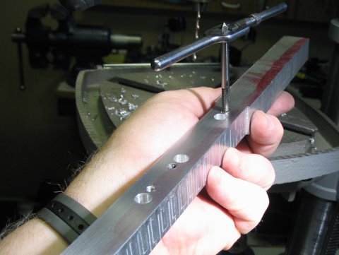
Tapped, drilled and counterbored
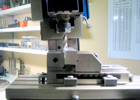
The mill was set 5 degrees off vertical to slope the sides of the piers
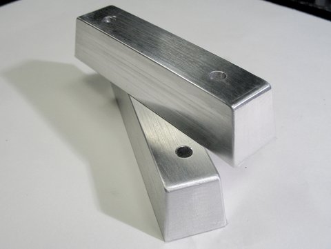
The finished piers awaiting surface treatment
After masking the bottoms and spending a short time in a ferric chloride bath
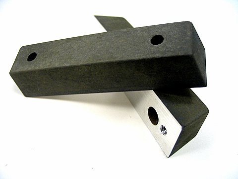
This gives the aluminium piers a good "roughed up" appearance(they can either take paint or stay as they are)
Here are the finished piers attached to the boiler skid:The piers can be attached / detached from underneathThe boiler skid is steel - the piers are aluminiumTo avoid pasing heat to the skid the bottom drum is cradled in two strips of cork. For a similar reason, no other part of the pressure vessel assembly actually touches the metal of the casing or the skid. As a result there isn't even electrical contact between the vessel and the casing. Just for fun I checked that out with an ohmmeter!
The next job was to install the baffle plates between some of the tube rows to direct the hot gases properly through the boiler and out the flue outlet. Then on to the burner, stack and boiler fittings.
I am still practicing taking pictures in the mirror!.jpg) The net result is an immensely distorted view and somewhat of a comic book chin! *
The net result is an immensely distorted view and somewhat of a comic book chin! *What is more important about the above picture is to note how the insulation encompases the furnace and convection bank areas of the boiler. I brought the top of the drum close to the casing because the safety valves and main steam outlet are located there. I am holding the unit at a slight angle - the drum is actually centrally located in the top section of the roof. A piece of insulation was not yet installed at the time of the photograph (under the small right slope section of the roof).
* I haven't beaten the camera's optical distortion of the lower part of my face yet. The camera is actually at upper-chest height and pointing up at a greater angle than it appears. I disguised by canting my head downward and looking into the camera's lens in order to appear to be looking straight at you. A mirror is not really a practical method for portraiture or most kinds of photography, since itputs things like my watch on the wrong hand and turns my Canon camera into a nonaC !
You are on Part 7
.jpg)
.jpg)
.jpg)
.jpg)
.jpg)
.jpg)
.jpg)
.jpg)
.jpg)
.jpg)
.jpg)