
John R. Bentley 2013-19.
Fabricating stainless steel
Fittings for the Methanol Tank
for the burner of the model D-type boiler
Jan 2013 - Oct 2019.
John R. Bentley 2013-19.
Fabricating stainless steel
Fittings for the Methanol Tank
for the burner of the model D-type boiler
First: the pressure relief valve
This relief valve is based on a design by Less Kerr that I saw in an article about a small methylated spirit burner in the 26 May-8 June 2006 issue of Model Engineer. Mine is larger due to a more sizable tank and proportions and materials are different, but the concept is the same.
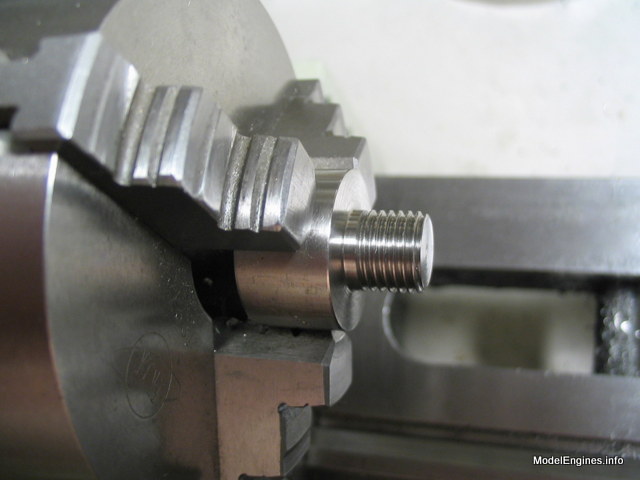
I was off to a great start, carefully cutting the thread on the stainless steel body. I used my Craftex mini lathe with a spindle crank for human power which provides better control and gives a good finish when cutting threads. I paid very close attention since I wanted a good smooth fit into the fuel tank top bush as this opening also serves as the fuel filler. All this fancy talk about precision and finish is just fine but attention to the basics is more important - I cut a left hand thread by mistake!
On the second attempt I got it right :-)
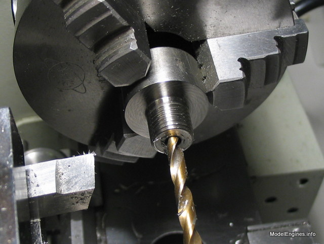
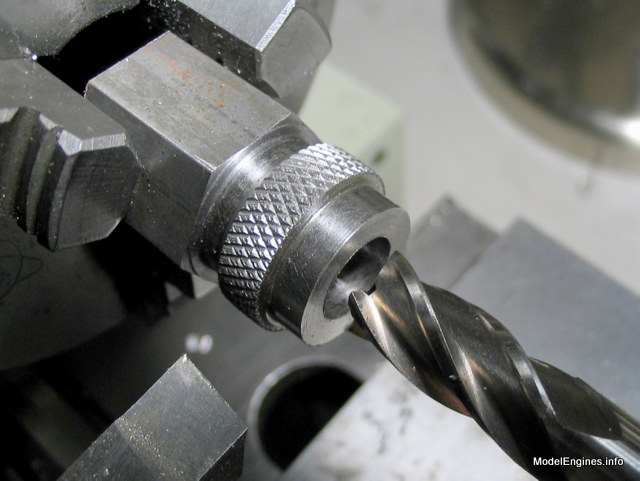
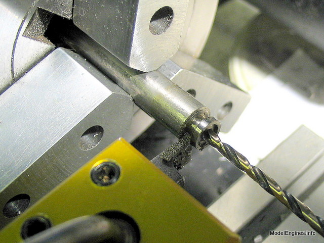
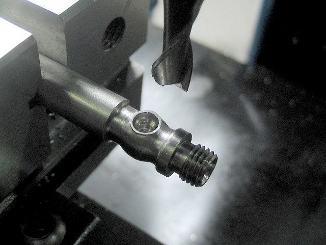
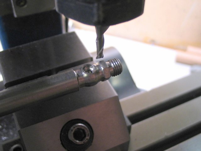
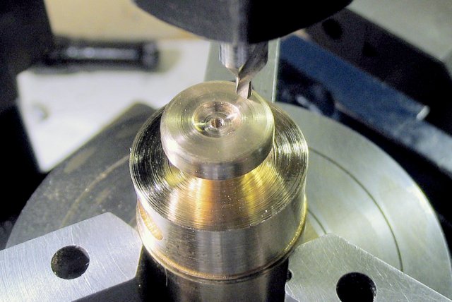
Drilling the body
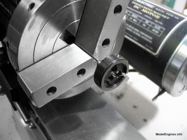
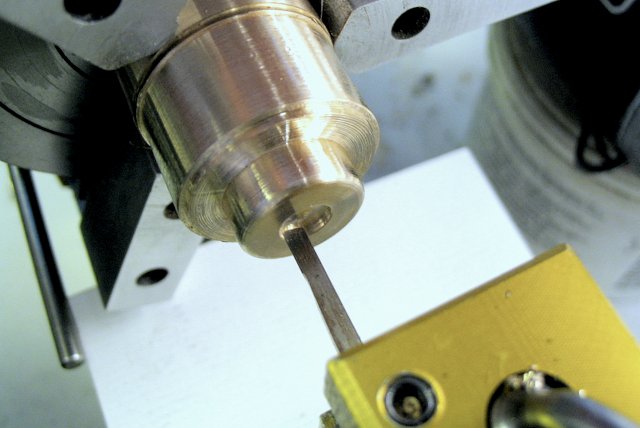
Making a sturdy threaded mandrel to hold the valve body for knurling
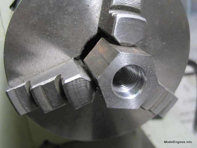
It seems to get an adquate grip
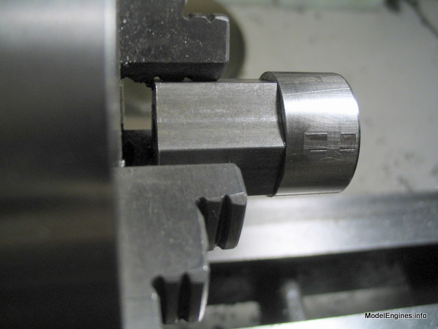
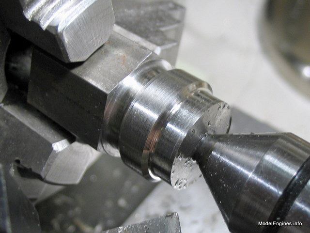
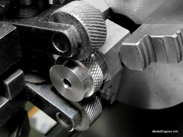
Profiled for the knurling operation with the outer end supported by the tailstock center
The valve body (center) squeezed between the two knurls in my Craftex mini lathe
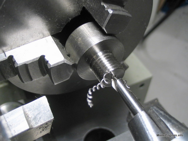
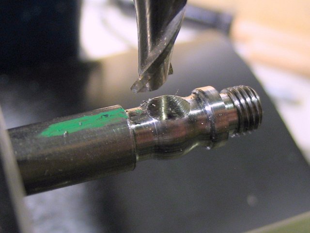
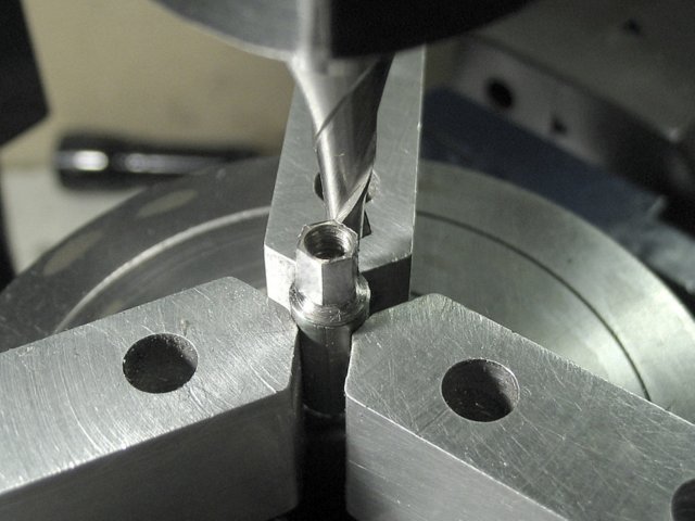
Flattening the bottom of the hole with an endmill
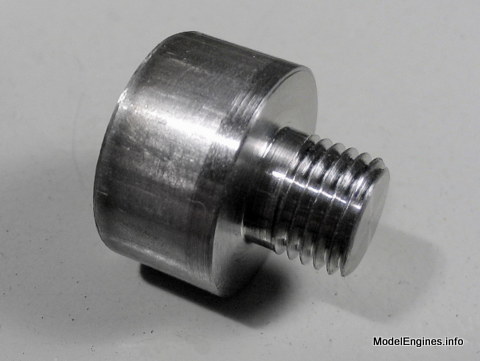
The completed body removed from its mandrel

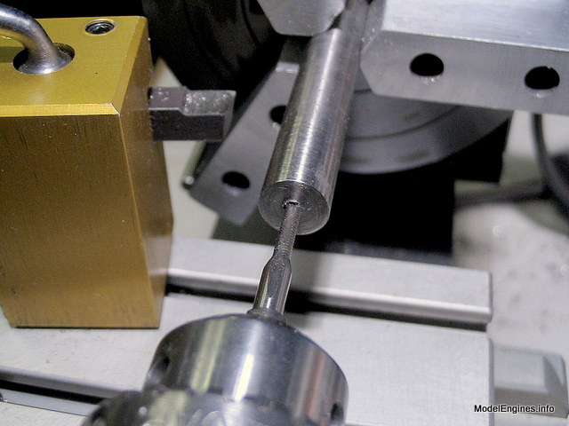
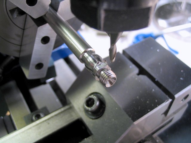
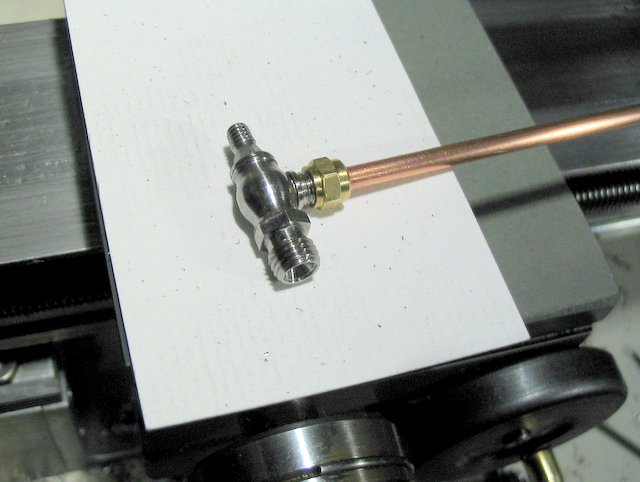
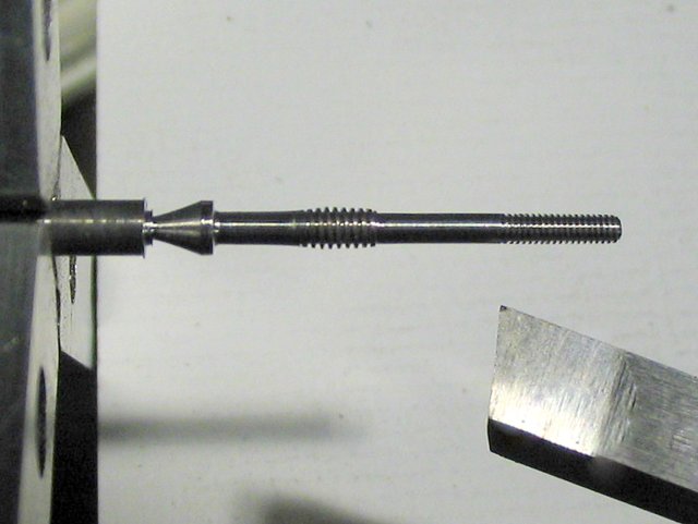
Threading the end of the valve spindle
Making an end retainer for the stainless steel valve spring
The few parts which make up the valve
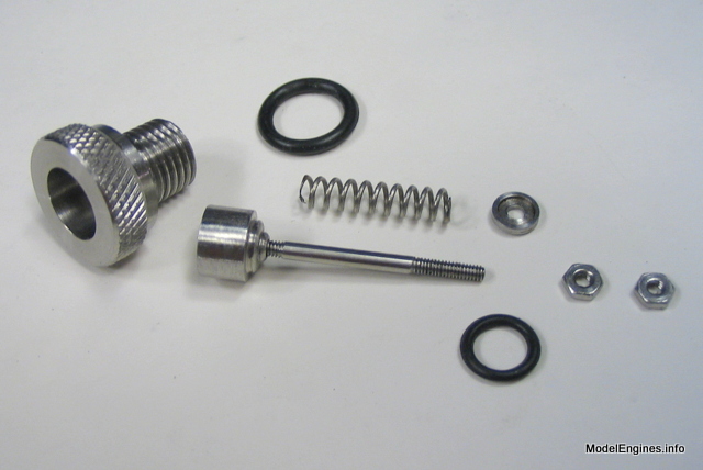
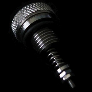
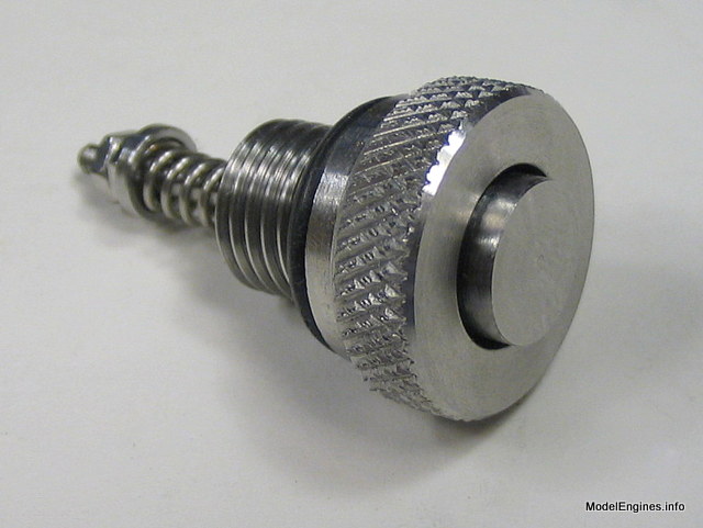
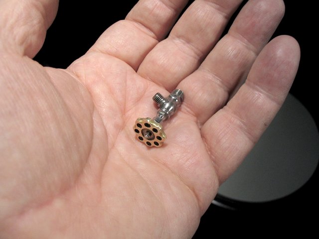
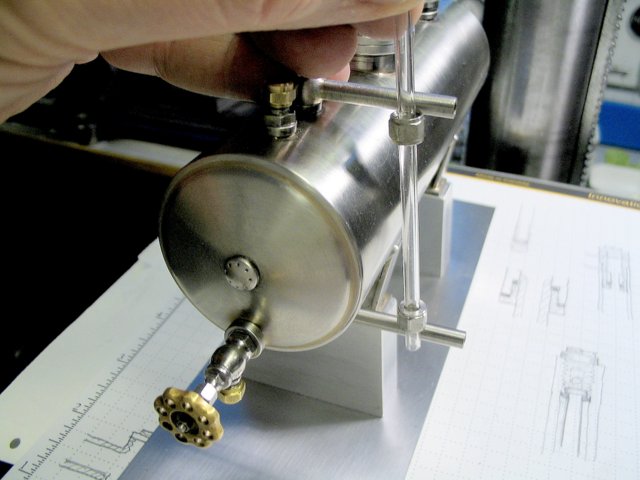
The following views show the finished relief valve for the methanol fuel tank
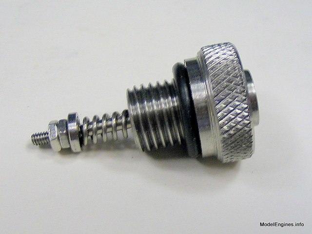
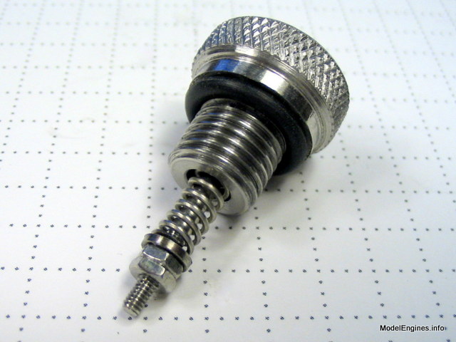
Pressure is relieved around the central piece which is the valve spindle
Next: the methanol tank valve
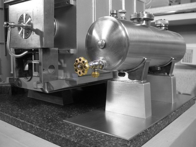
As this will be the fuel regulator and main tank shutoff a large handle is appropriate
This valve is an adaption of a simple screw down needle valve
It is not really very big
The body was turned from stainless steel in a Taig lathe
A flat was milled and a hole drilled to mount the spigot
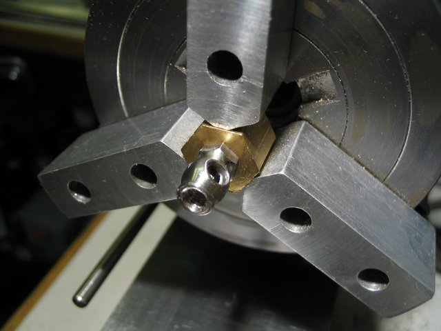
Milling a hex section at the base of the valve body
The completed hex
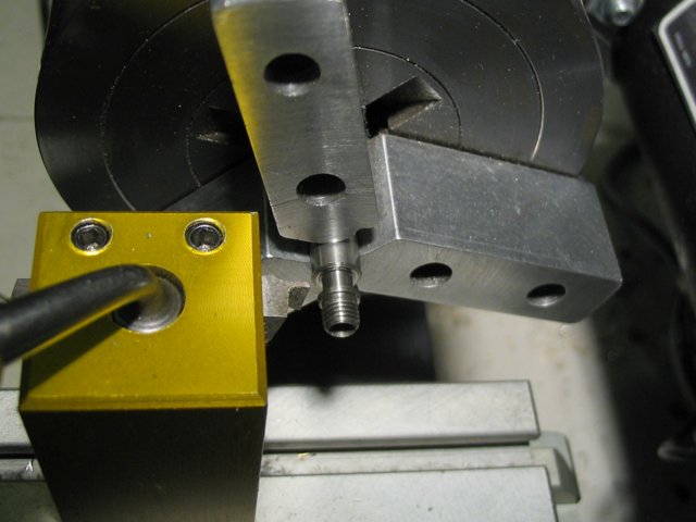
Valve body parted off from stock and held in a brass mandrel for drilling and threading
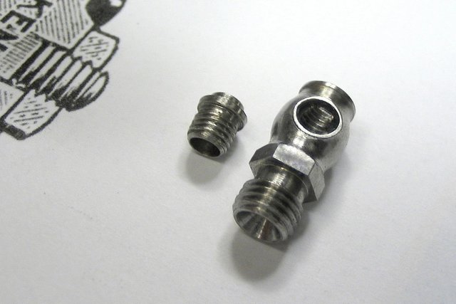
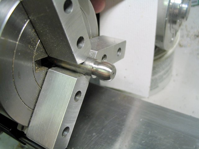
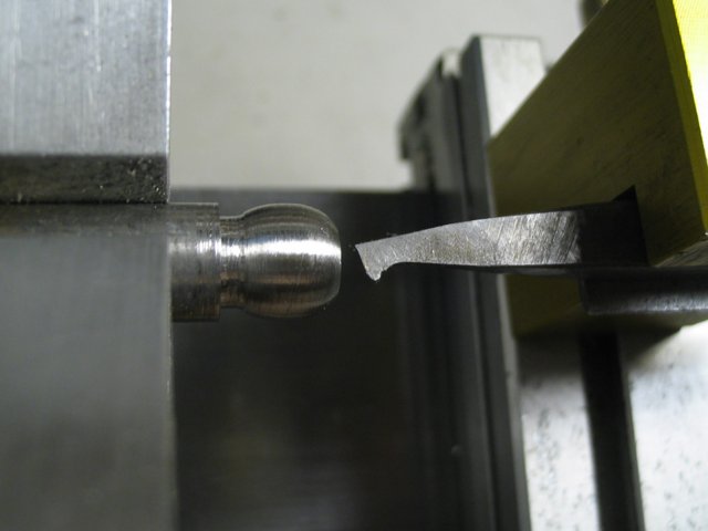
Making the spigot
Spigot and body to be silver brazed together
Starting to look like a valve (I hope)
Turning the valve spindle
Making the packing nut for the top
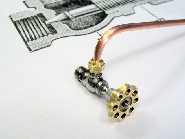
Turning the handle from naval brass
I copied a very common North American handle design
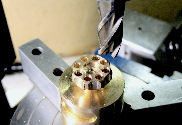
Milling the flutes
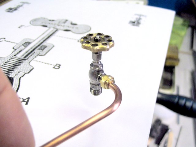
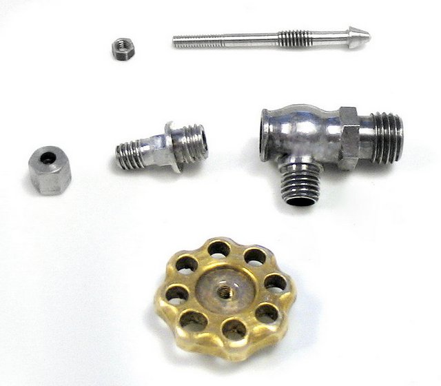
All the valve components (with the spigot already attached to the body)
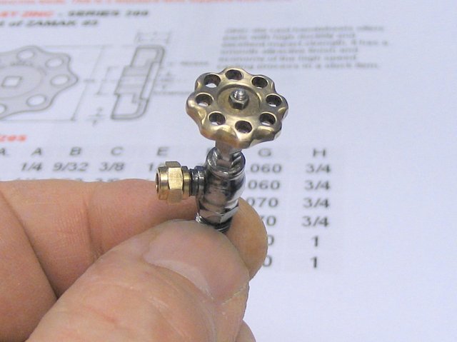
The completed valve
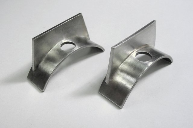
Tank mounting: Saddles and Piers
The saddles are located and held against the shell by bolting into blind threaded bushes in the bottom of the tank
Drilling the positioning holes
Fitting the saddle curves to match the tank's shell
(the near one still needs a bit of adjustment)
Lower supporting ribs

Ribs silver brazed into position
Two small plates will be brazed on the sides of each assembly
Facing mill preparing aluminum stock for the piers
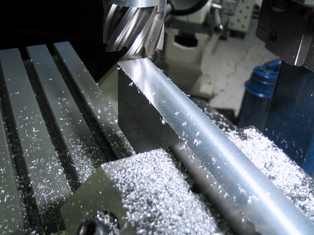
Piers to be drilled and tapped (on tops and bottoms)
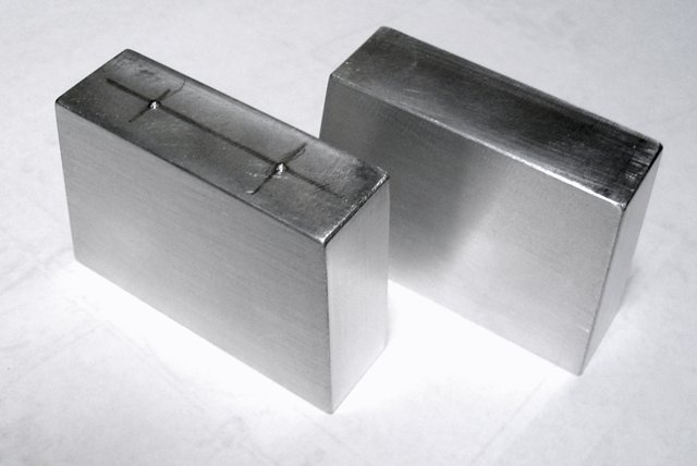
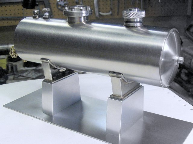
Completed saddles and piers bolted to a steel baseplate
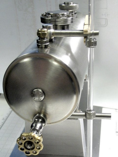
Next: the fuel level indicator

This is a pressurized fuel tank, not a steam boiler. The requirement of a gauge glass in a boiler is to show only the safe range of water levels. However a fuel gauge has a somewhat different job. Like those in our cars it must indicate how much fuel is remaining in the tank. Therefore it must display the entire range from full to completely empty.
With this in mind I decided to simply use a very long gauge glass at the side of the tank with the visible portion spanning the complete distance from top to bottom. The fuel level of course will not give a linear indication of the volume of fuel since the tank is widest at the mid point and infinitely narrow at the bottom and top. It also means that the very long glass is located where it will be suseptable to being smashed easily and so will require some physical protection.
A banjo joint at the top and bottom of the shell will suit this arrangement nicely
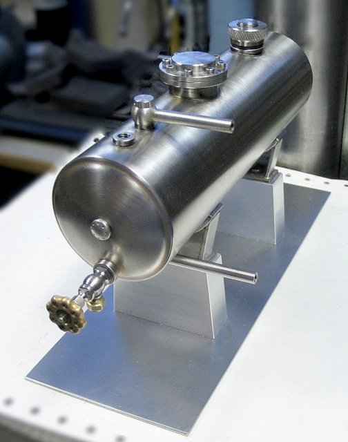
The upper banjo connection is visible in this view
Banjo connections are reasonably easy to construct and offer a couple of advantages over many other types. Orientation is easily set (or changed) as direction does not depend on thread tightness or washer thickness. The other feature is that banjos can be installed by simply sliding in over a suitable threaded bush. My fuel gauge glass assembly can slide in from the side over the top and bottom tank openings simultaneously as a rigid one-piece unit.
Turning one of the slightly oval banjo bodies
The oval shape was to aid in mounting a pipe on the side
Reaming the drilled hole through the body

Using an odd shaped tool to create a hollow body
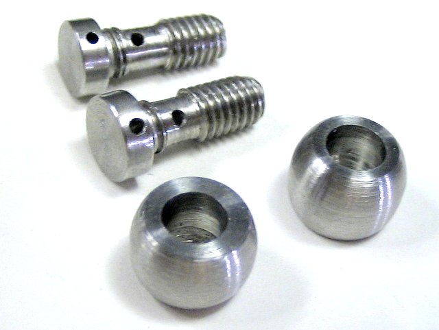
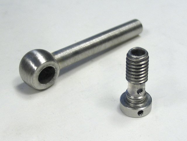
Creating banjo bolts from stainless steel screws

Left: original screw; Middle: head reduced; Right finished banjo bolt
The holes in the heads are for a tommy bar to tighten the bolts
(hex heads would be a suitable option)
A length of tubing silver brazed to the body completes one banjo unit
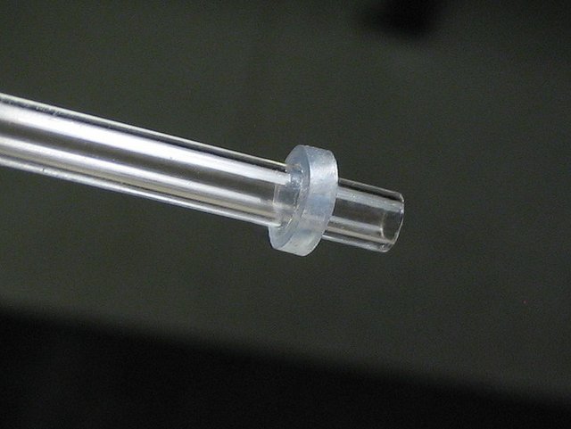
Cutting silicone washers for the gauge glass from model airplane fuel tubing
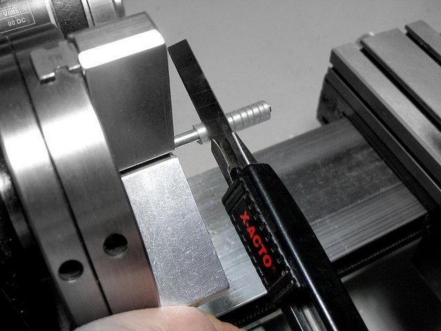
A few extras for some future project
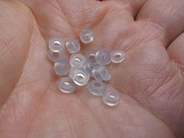
I have used this type of gage glass packing washer for years
- they work well without any problems
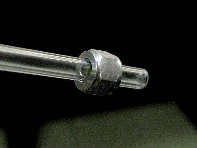
A stainless steel nut to slide over the silicone packing washer
Yet to be finished are elbows and protection rods for the glass
You are on Part 11