
John R. Bentley 2009.
2008 - 2009.
John R. Bentley 2009.
Forced Air Burner Assembly
- For the Model Watertube Boiler -
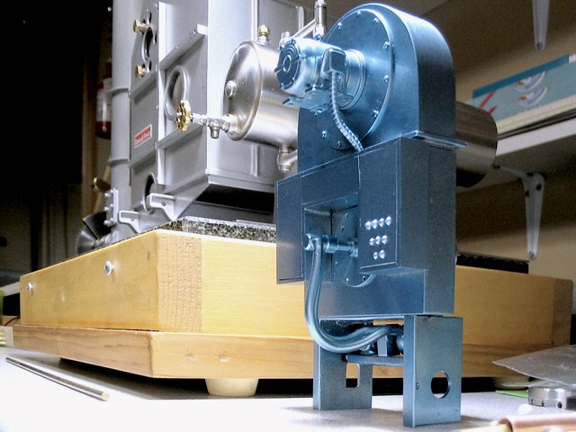
The burner and boiler face with piping and accessories yet to be added
To recap, the bare boiler pressure vessel, casing and stack were completed
before the beginning of Summer. This Autumn I started on the burner and
windbox assembly. A Cleaver Brooks BR burner type from the late 1970's is
being used as a rough guide, but it will not be an exact scale replica of any
particular one of their three BR versions.
Don't expect anything too clean and neat to be shown in these
pics - raw fabricating is still the rough
work:-)
The BR was one of three types
that were available in the period I have chosen for my model. I have
the company's simplified drawings with dimensions. I plan to follow these
as to proportions, but I'll reserve the privilege to only use them as an approximate
guide, since my fuel is different and some excessively small details are not
appropriate to a boiler that is to be used as a shop test unit.
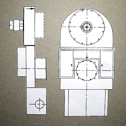
Here is a view of a Cleaver Brooks
packaged boiler burner from a 43-year-old brochure
.jpg) I will make this burner in two parts
that will push together - the top fan unit and the lower
burner/plenum/control box assembly. Not shown in this picture is a
fold-down operator's platform at the level of the bottom of the legs in front of
the fuel train.
I will make this burner in two parts
that will push together - the top fan unit and the lower
burner/plenum/control box assembly. Not shown in this picture is a
fold-down operator's platform at the level of the bottom of the legs in front of
the fuel train.
- note: the above image was taken from old Cleaver Brooks brochure and is included here under a fair use policy only to demonstrate the direction I am following in this hobby project. I will not do battle with anyone representing the company on this matter and will willingly give further credit or remove the image upon their request.
Paper cutouts were my starting point
The very first
brazed joint of the building season!It's the bottom corner of the
air plenum (just above the left leg)
It is being brazed over the
edge of the anvil on my vise
.jpg) Air
plenum
with backplate
installed
Air
plenum
with backplate
installed
.jpg) Ready for brazing in
the frontplate (left)
Ready for brazing in
the frontplate (left)
.jpg) Note the backplate is two overlapping
pieces. This is to help reduce air leaks since the bottom half
will slide out for lighting and servicing.
Marking out the fan housing
on steel plate
Note the backplate is two overlapping
pieces. This is to help reduce air leaks since the bottom half
will slide out for lighting and servicing.
Marking out the fan housing
on steel plate
.jpg) Bending the
edge
Bending the
edge
.jpg) This is stiff steel -
needless to say I didn't bend it around that plate, but used a heavy piece of pipe.
The windbox in waiting:
Some basic pieces for the blower and
air plenum
This is stiff steel -
needless to say I didn't bend it around that plate, but used a heavy piece of pipe.
The windbox in waiting:
Some basic pieces for the blower and
air plenum
.jpg) The unbrazed
mockup
The unbrazed
mockup
.jpg) Silver brazed fan
guard
(back view)
Silver brazed fan
guard
(back view)
.jpg) Front
view
Front
view
.jpg) Backplate brazed-in and chain-drilled for
removal of the fan opening
Backplate brazed-in and chain-drilled for
removal of the fan opening
.jpg) Back view of the front
plate and spacer
Back view of the front
plate and spacer
.jpg) Cracks left for
brazing
Cracks left for
brazing
.jpg) Rough brazed - nearly
finished
- except for large rectangular
flange around the bottom
Rough brazed - nearly
finished
- except for large rectangular
flange around the bottom
.jpg) (The color you are starting to see
is copper plating from the brazing pickle)
Making the
flange
(The color you are starting to see
is copper plating from the brazing pickle)
Making the
flange
.jpg) Cutting out on the
bandsaw
Cutting out on the
bandsaw
.jpg) Chain drilling fan housing
frontplate
(note the flange is
installed)
Chain drilling fan housing
frontplate
(note the flange is
installed)
.jpg) About to start making the four large openings in
the windbox assembly
I love old black and whites
About to start making the four large openings in
the windbox assembly
I love old black and whites
.jpg) This will be the front hole of the burner, visible on
the completed boiler
(it will be covered by a flat circular plate with a small fuel
tube entering the centre)
More chain-drilling
This will be the front hole of the burner, visible on
the completed boiler
(it will be covered by a flat circular plate with a small fuel
tube entering the centre)
More chain-drilling
.jpg) Hacking out the hole for the blower
(a larger flat plate will cover it with the motor
protruding from the centre)
Hacking out the hole for the blower
(a larger flat plate will cover it with the motor
protruding from the centre)
.jpg) Using a Sherline boring head in the Taig mill to
smooth out that mess
Using a Sherline boring head in the Taig mill to
smooth out that mess
.jpg) Boring completed
(some copper plating from the pickle is still remaining)
Boring completed
(some copper plating from the pickle is still remaining)
.jpg) The prototype burner has three electrical control
boxes mounted on the front
I am including them just in case I need space for any hidden
connections
The prototype burner has three electrical control
boxes mounted on the front
I am including them just in case I need space for any hidden
connections
.jpg) The frame is tacked with silver solder
The frame is tacked with silver solder
.jpg) I haven't progressed with these electrical cabinets too far to date -
the front doors are cut but not yet mounted
I haven't progressed with these electrical cabinets too far to date -
the front doors are cut but not yet mounted
.jpg) The three main fabricated components for the BR
Burner
(there is a two-legged assembly yet to be attached to the bottom
and possibly as well - a folding front platform, a signature
Cleaver Brooks option)
The three main fabricated components for the BR
Burner
(there is a two-legged assembly yet to be attached to the bottom
and possibly as well - a folding front platform, a signature
Cleaver Brooks option)
.jpg) The burner tube under construction
I turned it from solid 12L14
steel
The burner tube under construction
I turned it from solid 12L14
steel
.jpg)
(it is stepped to match various layers on
the windbox)
This will be the connecting tube between the
burner assembly and the firehole in the front of the
boiler casing. It will carry gaseous fuel and air through the addition of venturis and
mixing tubes.
Boring the
passage
.jpg) Back view of the burner
tube
(the super thin part at top enters the
boiler's firehole)
Back view of the burner
tube
(the super thin part at top enters the
boiler's firehole)
.jpg) (that pic is a bit fuzzy - I took
it while having lunch in a restaurant and the light was
limited)
Here's the tube screwed to
the back of the lower portion of the windbox
(note that the burner's bottom leg
assembly is seen here on the right side)
(that pic is a bit fuzzy - I took
it while having lunch in a restaurant and the light was
limited)
Here's the tube screwed to
the back of the lower portion of the windbox
(note that the burner's bottom leg
assembly is seen here on the right side)
.jpg) Drilling the blower front cover
plate
(in the Taig mill)
Drilling the blower front cover
plate
(in the Taig mill)
.jpg) Completed blower front plate with
motor attached
(the brass pinion will be removed and the
wires re-routed outside)
Completed blower front plate with
motor attached
(the brass pinion will be removed and the
wires re-routed outside)
.jpg) Trial of unfinished blower motor
on the upper portion of the windbox
Trial of unfinished blower motor
on the upper portion of the windbox
.jpg) Size reference: comparing to a
loupe
(the motor housing is still not yet
completed in this shot)
Size reference: comparing to a
loupe
(the motor housing is still not yet
completed in this shot)
.jpg) Adding detail to motor end cover
Adding detail to motor end cover
.jpg) North American electric motors with front flange (C-face)
mounting often include the bottom mount as well. The horizontal mount is a
great convenience when placing a large and heavy motor on a bench for servicing.
The thought of a 200 lb motor rolling onto a concrete floor is not pleasant
:-)
Starting to make the motor's bottom cradle and
mounting foot
North American electric motors with front flange (C-face)
mounting often include the bottom mount as well. The horizontal mount is a
great convenience when placing a large and heavy motor on a bench for servicing.
The thought of a 200 lb motor rolling onto a concrete floor is not pleasant
:-)
Starting to make the motor's bottom cradle and
mounting foot
.jpg) Bored to fit around the motor housing
Milling the bottom flat
Bored to fit around the motor housing
Milling the bottom flat
.jpg) Test fit on the shell
Test fit on the shell
.jpg) Bottom plate - to later become the mounting
feet
(high-temperature silver brazed to avoid coming apart during
subsequent brazing)
Bottom plate - to later become the mounting
feet
(high-temperature silver brazed to avoid coming apart during
subsequent brazing)
.jpg) Motor housing slowly coming
together!
Motor housing slowly coming
together!
.jpg) A mock-up of how it will look
A mock-up of how it will look
.jpg) Starting to make the motor electrical connection
box
(off-centre turning by using square stock in a 3-jaw chuck - I
use this trick often)
Starting to make the motor electrical connection
box
(off-centre turning by using square stock in a 3-jaw chuck - I
use this trick often)
.jpg) A rectangular loop of soft iron wire has been formed
and mounted diagonally
Fluxed and ready for brazing
A rectangular loop of soft iron wire has been formed
and mounted diagonally
Fluxed and ready for brazing
.jpg) Setting up for silver brazing the box on the right to
the motor
Setting up for silver brazing the box on the right to
the motor
.jpg) Whacking in pins to suggest motor bolt hole
locations
(I really don't know the word for those things... lugs?
bosses? ...)
Whacking in pins to suggest motor bolt hole
locations
(I really don't know the word for those things... lugs?
bosses? ...)
.jpg) On many motors with there is a strengthening
rib cast-in
across the diameter of the rear end
bell
(I have banged in two plates which will be subsequently
milled down)
On many motors with there is a strengthening
rib cast-in
across the diameter of the rear end
bell
(I have banged in two plates which will be subsequently
milled down)
.jpg) (a lot to finish yet)
A quarter-inch endmill does the
trick
(a lot to finish yet)
A quarter-inch endmill does the
trick
.jpg) Trying the wiring through the electrical box on the
side
Trying the wiring through the electrical box on the
side
.jpg) (the motor is a very common 4-6v Mabuchi model used in optical
disk drive drawer mechanisms (DVDs) and they are widely available. I have
three new units)
A quick coat of high-temperature paint to check out
the appearance
(the motor is a very common 4-6v Mabuchi model used in optical
disk drive drawer mechanisms (DVDs) and they are widely available. I have
three new units)
A quick coat of high-temperature paint to check out
the appearance
.jpg) In the scheme of things, visually this is a small and
insignificant part of the boiler
(I didn't take the detail beyond more than
an approximation of a typical 1970's motor)
In the scheme of things, visually this is a small and
insignificant part of the boiler
(I didn't take the detail beyond more than
an approximation of a typical 1970's motor)
.jpg) The front face threaded mounting holes are visible
here
The front face threaded mounting holes are visible
here
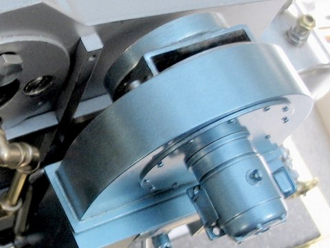
.jpg) In position on the blower
In position on the blower
.jpg) A rough mock-up of the entire burner lying
flat
A rough mock-up of the entire burner lying
flat
.jpg) If the operator's standing platform is added to this model, it
will extend out from below the bottom of the "legs" which are well above the
floor. A piece of armoured cable will extend from the bottom of the
electrical box on the motor's right side, straight down to the U-shaped control
boxes below. Of course there will be considerable fuel piping in the lower
area for the vaporizer and burner as well as the return connection to the
tank. There might be piezoelectric ignition or I may just use a
match.
Here is the view a person would see if approaching a
full size version of the boiler
If the operator's standing platform is added to this model, it
will extend out from below the bottom of the "legs" which are well above the
floor. A piece of armoured cable will extend from the bottom of the
electrical box on the motor's right side, straight down to the U-shaped control
boxes below. Of course there will be considerable fuel piping in the lower
area for the vaporizer and burner as well as the return connection to the
tank. There might be piezoelectric ignition or I may just use a
match.
Here is the view a person would see if approaching a
full size version of the boiler
.jpg) This is to be a working unit and not really a model, so heavy
steel materials were used to fabricate a durable unit at the expense of anything
like perfect scale or detail. I simply wanted something that looks like a
boiler plant for testing or demonstrating runs of my smaller engines. I
can't fix a proper time frame, since my range of models spans different eras, so
I felt an old-fashioned-looking, modern boiler might be preferred to a
modern-looking, old-fashioned boiler. If I want it to look modern I will
paint it Cleaver Brooks' light metallic blue and if I want it old, I can paint
it flat black and leave some shiny brass fittings.
Testing out methods of making armoured
cable
This is to be a working unit and not really a model, so heavy
steel materials were used to fabricate a durable unit at the expense of anything
like perfect scale or detail. I simply wanted something that looks like a
boiler plant for testing or demonstrating runs of my smaller engines. I
can't fix a proper time frame, since my range of models spans different eras, so
I felt an old-fashioned-looking, modern boiler might be preferred to a
modern-looking, old-fashioned boiler. If I want it to look modern I will
paint it Cleaver Brooks' light metallic blue and if I want it old, I can paint
it flat black and leave some shiny brass fittings.
Testing out methods of making armoured
cable
.jpg) Earlier that day this was an aluminum knitting
needle...
Drilling it out for the wire to pass
through
Earlier that day this was an aluminum knitting
needle...
Drilling it out for the wire to pass
through
.jpg) This is only a trial piece - I'll make a better
one :-)
This is only a trial piece - I'll make a better
one :-)
.jpg) Here is the approximate position it will
take
Here is the approximate position it will
take.jpg) A junction box at the loose end will hold it secure. Then
a moving contact on the lower removable part of the burner assembly will make
the connection when the burner is pushed into position.
I felt it was time to start making moving parts for the blower -
a change is as good as a rest they say.... I am
including a few more pictures:
Impeller
I knew that someday my boiler burner blower would need one, so I
made a start a couple of days ago:
Lopping off a block of 6061 Aluminum
A junction box at the loose end will hold it secure. Then
a moving contact on the lower removable part of the burner assembly will make
the connection when the burner is pushed into position.
I felt it was time to start making moving parts for the blower -
a change is as good as a rest they say.... I am
including a few more pictures:
Impeller
I knew that someday my boiler burner blower would need one, so I
made a start a couple of days ago:
Lopping off a block of 6061 Aluminum
.jpg) Turning a chucking piece on the end
Turning a chucking piece on the end
.jpg) Starting to form the impeller eye
Starting to form the impeller eye
.jpg) 1/4" ball endmill
1/4" ball endmill
.jpg) The beginning cuts for the first
blade
The beginning cuts for the first
blade
.jpg) Three blade segments roughed out
Three blade segments roughed out
.jpg) The initial cuts complete
The initial cuts complete
.jpg) Round Two
(these short cuts are parallel to the other sides of the
blades)
Round Two
(these short cuts are parallel to the other sides of the
blades)
.jpg) Nearly complete - yet to be accurately
sized
Nearly complete - yet to be accurately
sized
.jpg) Propping up the Dollar !
Propping up the Dollar !
.jpg) A sense of the scale
A sense of the scale
.jpg) It fits in the opening but it is still somewhat
too deep
It fits in the opening but it is still somewhat
too deep
.jpg) The blades have an angle to the radii to "cut" the air as it enters the eye
(note how they don't point directly toward the shaft
stem)
The blades have an angle to the radii to "cut" the air as it enters the eye
(note how they don't point directly toward the shaft
stem)
.jpg) Rotation: clockwise
At this point I began trimming the impeller to
size
Rotation: clockwise
At this point I began trimming the impeller to
size
.jpg) Then an oversight led to a horrible event -
You will notice that I forgot to engage the tailstock centre
into the shaft hole on the impeller! Part way along, the tool dug in,
swivelled the toolpost into the job and that little fan went into orbit,
rocketing over my right shoulder at the square of the speed of light.
I wasn't wearing my face mask, I was alone in the house - but I
was very fortunate. However a day-and-a-half's work on the wheel was put
into jeopardy. I should have used the Taig lathe for this job, but it was clean at the time and I
didn't want to get it dirty.
Of course that old fan never quite looked
the same again!
Then an oversight led to a horrible event -
You will notice that I forgot to engage the tailstock centre
into the shaft hole on the impeller! Part way along, the tool dug in,
swivelled the toolpost into the job and that little fan went into orbit,
rocketing over my right shoulder at the square of the speed of light.
I wasn't wearing my face mask, I was alone in the house - but I
was very fortunate. However a day-and-a-half's work on the wheel was put
into jeopardy. I should have used the Taig lathe for this job, but it was clean at the time and I
didn't want to get it dirty.
Of course that old fan never quite looked
the same again!
.jpg) (Repeating for emphasis)
(Repeating for emphasis)
.jpg)
.jpg) A monument to my sloppiness
A monument to my sloppiness
.jpg) I had a long think and decided to try to repair the device
before throwing in the towel and starting from scratch. (I am trying
to save the rest of that 6061 Aluminum bar for some future IC
engine) So back it went, into the lathe to be turned down to
size, after straightening the blades with a screwdriver.
This time I used the centre!
I had a long think and decided to try to repair the device
before throwing in the towel and starting from scratch. (I am trying
to save the rest of that 6061 Aluminum bar for some future IC
engine) So back it went, into the lathe to be turned down to
size, after straightening the blades with a screwdriver.
This time I used the centre!
.jpg) The outcome is a usable impeller
The outcome is a usable impeller
.jpg) It still seems to spin well on its shaft, so I think
the initial balance is OK
It still seems to spin well on its shaft, so I think
the initial balance is OK
.jpg) Next thing is the intake housing and a start on the steam
turbine housing, which will drive this impeller.
The egg-shaped intake housing plate
(the back side)
Next thing is the intake housing and a start on the steam
turbine housing, which will drive this impeller.
The egg-shaped intake housing plate
(the back side)
.jpg) The impeller blades fit between the two raised
rings
The impeller blades fit between the two raised
rings
.jpg) Impeller sitting in position on the inner side of the intake plate
Impeller sitting in position on the inner side of the intake plate
.jpg) It will look like this, but an air scoop will cover
the eye
It will look like this, but an air scoop will cover
the eye
.jpg) Air scoop roughed out
Air scoop roughed out
.jpg) Air scoop brazed in position on the intake plate
(a plate and the turbine casing will cover the "U" except
for a rectangular air intake at the top)
Air scoop brazed in position on the intake plate
(a plate and the turbine casing will cover the "U" except
for a rectangular air intake at the top)
.jpg) Overall shot of the back of the burner
Overall shot of the back of the burner
.jpg) Starting the steam turbine housing from stainless
steel
Starting the steam turbine housing from stainless
steel
.jpg) I think high polish will be beneficial - considering
the speed of the turbine
I think high polish will be beneficial - considering
the speed of the turbine
.jpg) The lathe's rotating centre is useful for parting off stainless steel
The lathe's rotating centre is useful for parting off stainless steel
.jpg) A parting shot
(we've all used that line before)
A parting shot
(we've all used that line before)
.jpg) The upper portion will look essentially like
this
(when the round turbine housing is brazed to the air scoop)
The upper portion will look essentially like
this
(when the round turbine housing is brazed to the air scoop)
.jpg) Probably I will silver braze three or more lugs to the outside of the turbine housing
Probably I will silver braze three or more lugs to the outside of the turbine housing
(to allow screwing on a back cover plate)
This view from above shows the rectangular air inlet
The back of the turbine housing is still not yet completed. A debris screen will cover the inlet opening, keeping flies
etc. from entering the duct and clogging the burner.
At this point in construction I really needed a change, so in the beginning of 2010 I started machining the castings for a Stuart Compound Launch engine which is covered elsewhere on this site. That job used most of a year and with other things happening work on this boiler didn't resume until the construction of the stainless steel fuel tank in late 2013.
You are on Part 9